
Solar Panel Wiring Diagram Guide: Configurations, Components & Best Practices
A solar panel wiring diagram is a fundamental guideline that guarantees a safe, efficient, and dependable solar energy system. From planning to installation, from residential to grid-tied projects, and even when it comes to battery storage, knowing how the various components fit together is crucial for performance and future expandability.
Solar wiring involves more than simply connecting panels together. Installers and system designers need to take into account wiring configurations, inverter connections, choice of wires, safety devices and energy storage requirements. Design choices can directly impact system efficiency, maintenance needs and long-term energy generation.
This guide will help you to understand how to read wiring diagrams for solar panels, select the appropriate wiring configuration, learn important electrical components, and prepare for a solar PV grid or battery integrated system. It also explores how modern energy storage and energy management technologies fit into today's solar installations.
Reading a Solar Panel Wiring Diagram
A solar panel wiring diagram is a schematic drawing that illustrates the connections and interactions between the electrical components in a solar power system. These diagrams illustrate how electricity generated by solar panels flows through the system, whether to the power meter, to a storage solution, or to the electrical grid.
From the simplest residential installation to the most advanced solar-plus-storage system, mastering how to read a wiring diagram is a necessary skill for system planning, troubleshooting and future upgrades.
Common Symbols Used in Solar Electrical Diagrams
A solar wiring diagram symbolically represents various components of the solar system using standard electrical symbols. Symbols can differ slightly from one manufacturer to the next and from one design software to another, but most diagrams will contain a representation of:
Solar panels
Inverters
Batteries
Charge controllers
Circuit breakers, isolators, Overcurrent devices, etc.
Utility grid connections
Monitoring equipment
Knowing these symbols helps installers easily identify the system layout and ensure that all necessary components are included in the design.
Understanding Current Flow and Circuit Layouts
Generally, solar electrical systems include direct current (DC) electricity produced by the solar cells and alternating current (AC) electricity required by the home appliances and the electrical grid. Wiring diagrams show the flow of electricity throughout the system, such as where DC electricity is converted to usable AC electricity.
When installing, it’s important that the installer can see how the system operates by tracing the flow of current and understanding the issues that may arise, ensuring components are connected properly.
Identifying Key System Components
Solar panel wiring diagrams feature a few key components essential for generating, converting, distributing, and controlling electricity.
Solar panels produce DC current, and an inverter converts it to AC current that can be used in the home. Other system elements may include charge controllers, batteries, monitoring devices and protection devices, depending on the system design.
Knowing the function of each element facilitates the analysis of various system designs and helps make wiring configuration decisions discussed in the next section.
Selecting the Right Wiring Configuration for Your System
Solar panel wiring configuration is a crucial aspect of solar system design. Panel layout will influence voltage, current, overall system efficiency, and compatibility with other system components like inverters and charge controllers.
There are many wiring configurations, each suited to different installation needs, so consider the project goals before choosing a configuration.
Solar Panel Wiring in Series Arrangements
In a series configuration, solar panels are arranged in series, such that the positive terminal of one solar panel is connected to the negative of the next.
In this arrangement, the system voltage is increased and the current remains the same. If higher voltage levels are needed to meet inverter/charge controller requirements, series wiring is often required.
Since all panels are on the same circuit, shading or performance problems with one panel can affect the output of the whole string.
Electrical Wiring for Solar Panels in Parallel Arrangements
A parallel configuration has the positive terminals of several panels connected together, and the negative terminals connected by a separate shared connection.
This method boosts the current level without changing the voltage. Partial shading can be mitigated by using parallel wiring, since each panel has its own impact on system performance. But the more current is required, the larger the cables and other protective equipment needed.
Combining Solar Panel Electrical Wiring in Series-Parallel Systems
In larger solar installations, series and parallel wiring are sometimes mixed to meet voltage and current requirements.
Series-parallel systems are typically utilized in residential and commercial systems where several strings of panels need to operate in parallel in the same system. This design will provide more flexibility and enable installers to optimise performance on larger arrays.
The specific configuration can vary based on the system's requirements and the available equipment.
Matching How to Wire Solar Panels to Project Requirements
No single wiring configuration is right for all projects. Various factors, like system size, cable runs, equipment compatibility, shading conditions and future expansion plans, all affect what design is best.
By knowing the right way to wire solar panels, you can ensure the wiring layout meets current performance needs and future system objectives.
Understanding and consequently selecting solar electrical system components is the next step in designing a solar electrical system, and the configuration selected also dictates the type of inverters, charge controllers, connectors and protection devices to be used.
Choosing Components for a Reliable Solar Wiring System
Solar power systems need proper solar panel electrical wiring to safely transfer electricity from the panels to the rest of the system.
DC isolators are typically used to provide the ability to disconnect parts of the system during maintenance, inspection or emergency conditions. To minimise energy losses and ensure the long term reliability of the system, correct cable sizing and routing are equally important.
Wiring and isolation equipment are essential to a safe solar electrical system.
Solar panels and DC isolators
Inverters are crucial components that convert the DC electricity produced by solar panels into AC electricity for use in homes and businesses.
Installers need to be aware that when designing electrical wiring for solar panels, the wiring layout must match the inverter specs, voltage limits, and system capacity. In addition, grid-tied inverters require appropriate protection devices and grid connection configurations to operate safely and efficiently.
The optimal choice of an inverter allows the maximum generation of energy from the system while maintaining stability.
Inverters and grid connections
Inverters are crucial components that convert the DC electricity produced by solar panels into AC electricity for use in homes and businesses.
Installers need to be aware that when designing electrical wiring for solar panels, wiring layouts need to match the inverter specs, voltage limits and system capacity. In addition, grid-tied inverters need the correct protection devices and grid connection set-ups to operate safely and efficiently.
The optimal choice of inverter allows the maximum generation of energy from the system while maintaining stability.
Charge controllers and battery interfaces
Battery storage introduces additional design considerations when determining how to wire solar panels within a complete energy system.
Charge controllers, battery interfaces, and communication equipment regulate the flow of energy from solar generation, through storage, to the home. The components should be chosen based on battery chemistry, system voltage, and the energy requirements.
With careful integration, both performance and long-term battery health are supported.
Solar panel extension wires and connectors
Strong links are critical to any solar installation. Good Solar Panel Extension Wires and Connectors ensure electrical performance and prevent issues caused by environmental factors such as moisture, UV rays, and temperature.
Extension cables that match the system's voltage and current ratings should be used by installers. The connections and compatibility between components are also crucial, as faulty connections can lead to increased resistance, decreased efficiency, and potential safety issues.
To ensure safe operation throughout the life of the system, cables and connectors should be used that have the appropriate rating for their intended application.
Planning Grid-Tied and Battery-Integrated Solar Systems
After deciding on the wiring design and the main solar power system components, the next step is planning the electricity in the larger solar power system.
The modern solar system can be grid-tied, battery-backed, or hybrid. The selected architecture will affect energy flows, equipment needs, and future expansion opportunities.
Grid-tied solar panel wiring diagrams
A solar panel grid-tie wiring diagram shows how solar panels, inverters, protection devices, and utility grid connections work together in a grid-connected installation.
A typical grid-tied installation converts the electricity produced by the solar panels into usable power for the building. If there is excess generation, it can then be exported to the grid (subject to grid configuration and local regulations). These systems are sometimes chosen for their simplicity and their use of available solar generation.
Solar panels with battery storage wiring diagrams
The wiring diagram for solar panels grid tie installation is useful for installers to see electric connections between the major components of the system.
This diagram generally contains solar arrays, solar isolators, solar inverters, consumer units and connections to the utility grid. Knowing the interactions between each part of the system can make planning for installation and future maintenance easier.
Thorough inspection of power grid wiring designs also guarantees adherence to applicable electrical requirements and standards.
Future expansion considerations
Solar panels with battery storage wiring diagrams include extra components that enable electricity to be stored for future use.
Battery-integrated systems can store excess solar generation and retrieve it for use during periods of greater demand or lower solar production, avoiding the need for exporting all of the excess generation to the grid.
Some of these wiring configurations may include battery connectivity, energy control systems, and communication networks to coordinate generation, storage, and usage.
Managing Energy Flow Between Generation, Storage, and Consumption
As solar systems become more advanced, energy flow management becomes increasingly important. Under certain conditions of the electricity system and user preferences, electricity can flow from the solar panels to battery storage, to household loads, or back to the grid.
It is sometimes desirable to plan for future energy requirements at the outset of any new installation. This can enable easier integration of battery storage, higher electricity loads, or further smart energy solutions at a later stage without redesigning the entire system.
Optimising Solar Systems with Storage and Energy Management
No longer are modern solar installations limited to generating electricity. Storage and energy management technologies are becoming a key component of system planning with more and more households seeking to optimise the solar self-consumption while at the same time increasing the overall energy efficiency.
As solar panel wiring diagrams are increasingly used to explore, battery storage systems and energy management infrastructure are often seen as part of the complete setup with solar panels, inverters, and the grid. These additions allow for a more flexible and responsive energy system.
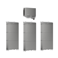
Example of Solar Storage Integration: PowerOcean Single-Phase
Solar panels with battery storage wiring diagram typically include battery storage alongside the solar generation system. This allows excess electricity produced during the day to be stored and used later when solar production is lower.
EcoFlow PowerOcean Single-Phase is ideal for residential solar storage and can be connected to a larger solar energy system. It's a scalable design, so homeowners can add storage as energy needs change to boost their solar self-consumption and support long-term energy planning.

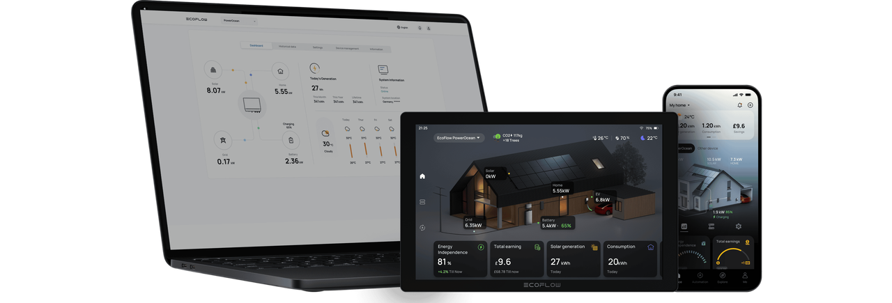
Coordinating Energy Use with EcoFlow Intelligent HEMS
As solar systems become more advanced, managing when and how electricity is used becomes just as important as generating it. An effective solar panel wiring diagram increasingly includes communication and monitoring pathways that support intelligent energy management.
With its energy monitoring and scheduling capabilities, EcoFlow Intelligent HEMS optimises the coordination of solar energy generation, energy storage, and household consumption. This will also help homeowners optimise their self-consumption and make more informed energy decisions, given greater clarity around the system.
Schedule Your Free Consultation Today!
What kind of product or solution are you interested in?
Conclusion
A solar panel wiring diagram is a crucial aspect of solar power system design, ensuring that the system is both safe, efficient, and reliable. Whether it's deciding on the appropriate wiring system, understanding component compatibility, or planning for grid-tied or battery storage solutions, every choice affects the system's performance and potential flexibility.
The design of a solar system is no longer just about connecting panels to the system; it continues to evolve with the advancement of solar technology. Homeowners can use battery storage and intelligent energy management to optimise the use of the electricity they generate and to meet energy goals.
With proper system design and installation, installers and homeowners can design solar systems that are efficient, scalable, and future-proofed for changing energy needs.
FAQs
What cable size is typically used for solar panel installations?
Selecting the proper cable size requires considering the system voltage, current, cable length, and local electrical requirements. In solar panel wiring, cable size is an important consideration: a smaller cable can cause voltage drop as electricity flows to the panels, which can affect the safe and efficient operation of the entire system.
Can solar wiring diagrams vary between inverter manufacturers?
Yes. While the basic principles remain similar, specific manufacturers may have their own preferred configurations, communication systems and security measures. Always check the solar panel wiring diagram for the solar panel provided with the inverter to ensure it's wired correctly.
What safety devices are commonly included in solar wiring systems?
Typically, solar installations have DC isolators, AC isolators, circuit breakers, surge protection, and an earthing system. These components ensure the safety of electrical systems, the protection of equipment, and ease in maintenance.
Can existing solar installations be upgraded to include battery storage?
In many cases, yes. Compatibility can vary depending on the inverter type, available battery capacity, and the requirements of the original solar panels and battery storage wiring diagrams, but existing systems can be upgraded to incorporate battery storage. If you wish to make any changes, a professional assessment is recommended.
What are the most common mistakes in solar panel wiring design?
Factors like incorrect cable sizing, incorrect connector selection, voltage drop issues, protection device issues, and lack of planning for subsequent system expansion are common. However, careful design and installation practices can help to avoid these problems.
How can energy management systems improve solar self-consumption?
Energy management systems can help manage electricity generation, storage, and consumption. Households can track their consumption and maximise the use of solar electricity to reduce the need for grid electricity.
What should be checked before modifying an existing solar wiring system?
Installers must check the compatibility of equipment, cable ratings, voltage limits, protection devices and manufacturer recommendations before making any changes. When planning the electrical wiring layout for solar panels, assess the current configuration to anticipate potential problems.

